

Lunar Orbiter Laser Altimeter (Spot Observations)
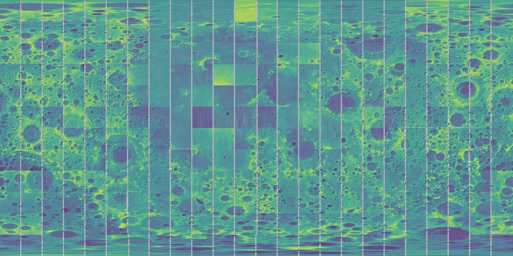
Figure 1: Sample gridded data created using PDAL . A browse thumbnail of each of the 288 tiles was created using QGIS. Artifacts (no data strips) between tiles are a product of the thumbnail creation and not indicative of missing data. Each thumbail is scaled independently, therefore color ramps vary by image tile.
These data can be accessed in three ways:
This cloud-optimized point cloud release provides data from the Lunar Orbiter Laser Altimeter (LOLA; Citation: Smith, Zuber & al., 2011 Smith, D., Zuber, M., Neumann, G., Mazarico, E., Head, J., Torrence, M. & Lola Science Team (2011). Results from the Lunar Orbiter Laser Altimeter (LOLA): Global, High Resolution Topographic Mapping of the Moon. 2350. Retrieved from https://ui.adsabs.harvard.edu/abs/2011LPI....42.2350S ), an instrument on the National Aeronautics and Space Administration (NASA) Lunar Reconnaissance Orbiter (LRO) spacecraft ( Citation: Tooley, Houghton & al., 2010 Tooley, C., Houghton, M., Saylor, R., Peddie, C., Everett, D., Baker, C. & Safdie, K. (2010). Lunar Reconnaissance Orbiter Mission and Spacecraft Design. Space Science Reviews, 150(1). 23–62. https://doi.org/10.1007/s11214-009-9624-4 ) . The data consists of over 6.3 billion measurements gathered between July 2009 and February 2023, adjusted for consistency in the coordinate system described below, and then converted to lunar radii ( Citation: Mazarico, Rowlands & al., 2012 Mazarico, E., Rowlands, D., Neumann, G., Smith, D., Torrence, M., Lemoine, F. & Zuber, M. (2012). Orbit determination of the Lunar Reconnaissance Orbiter. Journal of Geodesy, 86(3). 193–207. https://doi.org/10.1007/s00190-011-0509-4 ) . Elevations above the sphere can be computed by subtracting the lunar reference radius of 1737.4 kilometers ( Citation: Group, 2008 Group, L. (2008). A standardized lunar coordinate system for the Lunar Reconnaissance Orbiter and lunar datasets: Lunar Reconnaissance Orbiter Project and Lunar Reconnaissance Orbiter Project Lunar Geodesy and Cartography Working Group White Paper, v. 5 . Retrieved from http://lunar.gsfc.nasa.gov/library/LunCoordWhitePaper-10-08.pdf ; Citation: Archinal, A’Hearn & al., 2011 Archinal, B., A’Hearn, M., Bowell, E., Conrad, A., Consolmagno, G., Courtin, R., Fukushima, T., Hestroffer, D., Hilton, J., Krasinsky, G., Neumann, G., Oberst, J., Seidelmann, P., Stooke, P., Tholen, D., Thomas, P. & Williams, I. (2011). Report of the IAU Working Group on Cartographic Coordinates and Rotational Elements: 2009. Celestial Mechanics and Dynamical Astronomy, 109(2). 101–135. https://doi.org/10.1007/s10569-010-9320-4 ; Citation: Archinal, Acton & al., 2018223 Archinal, B., Acton, C., A'Hearn, M., Conrad, A., Consolmagno, G., Duxbury, T., Hestroffer, D., Hilton, J., Kirk, R., Klioner, S., McCarthy, D., Meech, K., Oberst, J., Ping, J., Seidelmann, P., Tholen, D., Thomas, P. & Williams, I. (2018, 2, 23). Report of the IAU Working Group on Cartographic Coordinates and Rotational Elements: 2015. Celestial Mechanics and Dynamical Astronomy, 130(3). 22. https://doi.org/10.1007/s10569-017-9805-5 ) from the surface radius measurements.
The LOLA instrument, as described by Citation: Smith, Zuber & al., 2011 Smith, D., Zuber, M., Neumann, G., Mazarico, E., Head, J., Torrence, M. & Lola Science Team (2011). Results from the Lunar Orbiter Laser Altimeter (LOLA): Global, High Resolution Topographic Mapping of the Moon. 2350. Retrieved from https://ui.adsabs.harvard.edu/abs/2011LPI....42.2350S , is a multibeam laser altimeter that illuminates 5 spots on the ground with each spot having a 5-meter diameter size (assuming nadir sensor orientation and no surface slope, and the initial nominal 50 km altitude for LRO). The center of each pulse in a 5-spot pulse is separated by approximately 20 m (and with a 5 m spot size, the true distance between spot edges is 10 m). The distance between 5-spot pulses is ~56 m.
The LRO spacecraft has always been in a near-polar orbit. Although the eccentricity of the orbit has changed several times over the mission to its current quasi-stable elliptical orbit varying the height of the spacecraft above the geoid between ~30 km to 200 km. For one year, during LRO’s primary mission phase, the spacecraft flew in a more circular orbit at a nominal height of 50 km above the geoid.
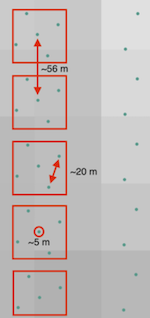
Figure 1: Five 5-pulese records (red boxes), with approximately 56 meters between each 5-pulse group, approximately 20 meters between each sub-pulse in a group. Each sub-pulse has a nominal, 5 meter diameter
The original LOLA data DOI:10.17189/1520640 was queried from the Planetary Data System (PDS) Geosciences Node’s LOLA RDR Query Tool, Version 2.0. This tool provides access to individual observations from the original LOLA archive . Data were downloaded in 15˚ x 15˚ (latitude/longitude) tiles. Once downloaded, the shots were converted from comma-separated value (CSV) format to the LAS file format. The LAS files were then compressed and converted to Cloud Optimized Point Cloud (COPC) using the untwine software tool. Once all processing was complete, Spatio-Temporal Asset Catalog (STAC) metadata were created for each tile. These data can and should be queried as a global data set, as tiling is a product of the incremental data download and for storage efficiencies.
“A COPC file is a LAZ 1.4 file that stores point data organized in a clustered octree” (\cite{COPC}). LAZ is a compressed LAS file format defined by the ASPRS (American Society for Photogrammetry and Remote Sensing) storing LiDAR data as points. This COPC file uses the ASPRS LAS Point Data version 1.4, Record Format 6. COPC, like cloud-optimized GeoTIFFs, allows for streaming huge point-clouds using simple HTTPS range requests.
These data are made available in the 2015 IAU 30100, Moon/Sphere/Ocentric coordinate system, with a center longitude of 0 and a longitude domain of -180˚ to 180˚, referenced to IAU recommended reference ellipsoid (sphere, 1737.400 km).
The LOLA data were initially referenced to an internally consistent inertial coordinate system, derived from tracking of the LRO spacecraft. By adopting appropriate values for the orientation of the Moon as defined by the International Astronomical Union ( Citation: Archinal, A’Hearn & al., 2011 Archinal, B., A’Hearn, M., Bowell, E., Conrad, A., Consolmagno, G., Courtin, R., Fukushima, T., Hestroffer, D., Hilton, J., Krasinsky, G., Neumann, G., Oberst, J., Seidelmann, P., Stooke, P., Tholen, D., Thomas, P. & Williams, I. (2011). Report of the IAU Working Group on Cartographic Coordinates and Rotational Elements: 2009. Celestial Mechanics and Dynamical Astronomy, 109(2). 101–135. https://doi.org/10.1007/s10569-010-9320-4 ) , these inertial coordinates were converted into the body-fixed body-centered (geocentric) XYZ coordinates. The coordinate system defined for this product is the mean Earth/polar axis (ME) system, sometimes called the mean Earth/rotation axis system. The ME system is widely used for cartographic products ( Citation: Davies & Colvin, 2000 Davies, M. & Colvin, T. (2000). Lunar coordinates in the regions of the Apollo landers. Journal of Geophysical Research: Planets, 105(E8). 20277–20280. https://doi.org/10.1029/1999JE001165 ) . Values for the orientation of the Moon were derived from the Jet Propulsion Laboratory Developmental Ephemeris (DE) 421 planetary ephemeris ( Citation: Williams, Boggs & al., 2008 Williams, J., Boggs, D. & Folkner, W. (2008). DE421 Lunar orbit, physical librations, and surface coordinates: Jet Propulsion Laboratory Interoffice Memorandum (IOM 335-JW,DB,WF-20130722-016). Jet Propulsion Laboratory, California Institute of Technology Retrieved from https://naif.jpl.nasa.gov/pub/naif/generic_kernels/spk/planets/de430_moon_coord.pdf ; Citation: Folkner, Williams & al., 2009 Folkner, W., Williams, J. & Boggs, D. (2009). The Planetary and Lunar Ephemeris DE 421 (IPN Progress Report 42-178). Retrieved from https://ipnpr.jpl.nasa.gov/progress_report/42-178/178C.pdf ) and rotated into the ME system.
- COPC file for 15˚ x 15˚ (longitude/latitude) tile.
The Lunar Orbiter Laser Altimeter (LOLA) aboard the Lunar Reconnaissance Orbiter (LRO) has collected over 6.3 billion measurements. The average accuracy of each point after crossover correction is better than 20 meters (m) in horizontal position and ~1 m in radius/elevation ( Citation: Mazarico, Rowlands & al., 2012 Mazarico, E., Rowlands, D., Neumann, G., Smith, D., Torrence, M., Lemoine, F. & Zuber, M. (2012). Orbit determination of the Lunar Reconnaissance Orbiter. Journal of Geodesy, 86(3). 193–207. https://doi.org/10.1007/s00190-011-0509-4 ) . Note that these reported accuracies and precision are a function of surface slope and roughness. As described by ( Citation: Neumann, 2011 Neumann, G. (2011). Lunar Reconnaissance Orbiter Lunar Orbiter Laser Altimeter Reduced Data Record and Derived Products Software Interface Specification . Retrieved from https://lunar.gsfc.nasa.gov/lola/images/LOLA_RDRSIS.pdf ) accuracy also decreases as the altitude of the spacecraft above the surface exceeds 50 km. Gaps between tracks of 1–2 km are common, and some gaps of as much as 4 km occur near the equator (as measured in the current data release using QGIS and ellipsoidal distances).
The LOLA data set does not preclude some qualitative issues with the data. First, LOLA data are most dense at the poles and least dense at the equator. The figure below illustrates LOLA equatorial coverage, with gap between LOLA tracks as large as 4 kilometers.
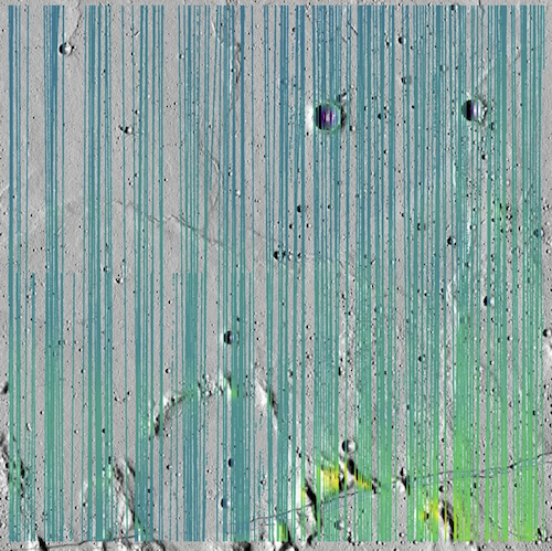
Figure 2: LOLA spot observations from this data set in the region -2˚ to 2˚N/S, and -2˚ to 2˚E/W. Gaps as large as 4km can be measured between LOLA tracks. While coordinates are stored in spherical degrees (Latitude/Longitude), QGIS uses a 2D equirectangular projection to display the LOLA tracks over an SLDEM2015/LOLA merge hillshade DOI: 10.17189/1520642 .
These gaps impact any gridded product that makes use of interpolation/extrapolation for fill. For example, the Figure below, 3, (generated using the Point Data Abstraction Library shows both data gaps and telltale interpolation errors. The inset image shows along-track (N/S) striping where the crater rim is most prominent in spot of true data and the true topographic relief is reduced where interpolated. A selected interpolation method should be chosen with care ( Citation: Barker, Mazarico & al., 2016 Barker, M., Mazarico, E., Neumann, G., Zuber, M., Haruyama, J. & Smith, D. (2016). A new lunar digital elevation model from the Lunar Orbiter Laser Altimeter and SELENE Terrain Camera. Icarus, 273. 346 – 355. https://doi.org/https://doi.org/10.1016/j.icarus.2015.07.039 ) .
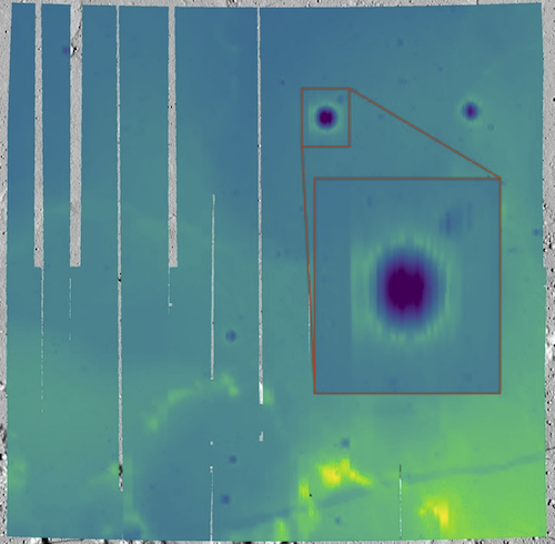
Figure 3: LOLA spot observations, gridded to a DTM, from this data set in the region -2˚ to 2˚N/S, and -2˚ to 2˚E/W. Interpolation artifacts are shown in the sub-image.
The Figure below,4, illustrates this by superimposing the spot observations over the gridded data product.
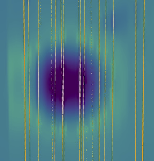
Figure 4: Inset image from Figure 3 showing the interpolation artifacts more clearly. Artifacts between tracks are created by interpolation.
Any user making use of these products to generate gridded Digital Elevation Models (DEMs) must take care to account for and report interpolation related artifacts.
This data product is well suited for use with tools requiring spot elevation information. For example, the NASA Ames Stereo Pipeline ( Citation: Beyer, Alexandrov & al., 2018 Beyer, R., Alexandrov, O. & McMichael, S. (2018). The Ames Stereo Pipeline: NASA’s Open Source Software for Deriving and Processing Terrain Data. Earth and Space Science, 5(9). 537–548. https://doi.org/https://doi.org/10.1029/2018EA000409 ) `pc_align tool can align a stereoscopically generated DTM to a sparse point cloud. These LOLA spot observations are well suited to be used as said reference DTM.
LOLA spot observations are the proxy product for the geodetic coordinate reference frame, a foundational lunar data product . Therefore, all other lunar data products which are geometrically (photogrammetrically and radargrammetrically) controlled should align (within reported errors of the LOLA data and the other data products themselves) with these LOLA spot observations. These spot observations are the inputs used for the derivation of many LOLA and LOLA-merge products. For example, the LOLA 118 m DEM, DOI: 10.17189/1520642 , derived hillshades ,merged product, DOI: 10.17189/1520642 . These products were all created using the LOLA spot observations available in this release.
These data are released under the CC0-1.0 license , meaning you can copy, modify, and distribution these data without permissions. We ask that you cite these data if you make use of them. The citation to be used is:
Laura, J.R. and Hare, T.M., 2023. Lunar Orbiter Laser Altimeter (LOLA) Reduced Data Record (RDR) Cloud Optimized Point Cloud (COPC) Data Release. https://doi.org/doi:10.5066/P9V5JIWH
- Archinal, B., A’Hearn, M., Bowell, E., Conrad, A., Consolmagno, G., Courtin, R., Fukushima, T., Hestroffer, D., Hilton, J., Krasinsky, G., Neumann, G., Oberst, J., Seidelmann, P., Stooke, P., Tholen, D., Thomas, P. & Williams, I. (2011). Report of the IAU Working Group on Cartographic Coordinates and Rotational Elements: 2009. Celestial Mechanics and Dynamical Astronomy, 109(2). 101–135. https://doi.org/10.1007/s10569-010-9320-4
- Archinal, B., Acton, C., A'Hearn, M., Conrad, A., Consolmagno, G., Duxbury, T., Hestroffer, D., Hilton, J., Kirk, R., Klioner, S., McCarthy, D., Meech, K., Oberst, J., Ping, J., Seidelmann, P., Tholen, D., Thomas, P. & Williams, I. (2018, 2, 23). Report of the IAU Working Group on Cartographic Coordinates and Rotational Elements: 2015. Celestial Mechanics and Dynamical Astronomy, 130(3). 22. https://doi.org/10.1007/s10569-017-9805-5
- Barker, M., Mazarico, E., Neumann, G., Zuber, M., Haruyama, J. & Smith, D. (2016). A new lunar digital elevation model from the Lunar Orbiter Laser Altimeter and SELENE Terrain Camera. Icarus, 273. 346 – 355. https://doi.org/https://doi.org/10.1016/j.icarus.2015.07.039
- Beyer, R., Alexandrov, O. & McMichael, S. (2018). The Ames Stereo Pipeline: NASA’s Open Source Software for Deriving and Processing Terrain Data. Earth and Space Science, 5(9). 537–548. https://doi.org/https://doi.org/10.1029/2018EA000409
- Davies, M. & Colvin, T. (2000). Lunar coordinates in the regions of the Apollo landers. Journal of Geophysical Research: Planets, 105(E8). 20277–20280. https://doi.org/10.1029/1999JE001165
- Folkner, W., Williams, J. & Boggs, D. (2009). The Planetary and Lunar Ephemeris DE 421 (IPN Progress Report 42-178). Retrieved from https://ipnpr.jpl.nasa.gov/progress_report/42-178/178C.pdf
- Group, L. (2008). A standardized lunar coordinate system for the Lunar Reconnaissance Orbiter and lunar datasets: Lunar Reconnaissance Orbiter Project and Lunar Reconnaissance Orbiter Project Lunar Geodesy and Cartography Working Group White Paper, v. 5 . Retrieved from http://lunar.gsfc.nasa.gov/library/LunCoordWhitePaper-10-08.pdf
- Mazarico, E., Rowlands, D., Neumann, G., Smith, D., Torrence, M., Lemoine, F. & Zuber, M. (2012). Orbit determination of the Lunar Reconnaissance Orbiter. Journal of Geodesy, 86(3). 193–207. https://doi.org/10.1007/s00190-011-0509-4
- Neumann, G. (2011). Lunar Reconnaissance Orbiter Lunar Orbiter Laser Altimeter Reduced Data Record and Derived Products Software Interface Specification . Retrieved from https://lunar.gsfc.nasa.gov/lola/images/LOLA_RDRSIS.pdf
- Smith, D., Zuber, M., Neumann, G., Mazarico, E., Head, J., Torrence, M. & Lola Science Team (2011). Results from the Lunar Orbiter Laser Altimeter (LOLA): Global, High Resolution Topographic Mapping of the Moon. 2350. Retrieved from https://ui.adsabs.harvard.edu/abs/2011LPI....42.2350S
- Tooley, C., Houghton, M., Saylor, R., Peddie, C., Everett, D., Baker, C. & Safdie, K. (2010). Lunar Reconnaissance Orbiter Mission and Spacecraft Design. Space Science Reviews, 150(1). 23–62. https://doi.org/10.1007/s11214-009-9624-4
- Williams, J., Boggs, D. & Folkner, W. (2008). DE421 Lunar orbit, physical librations, and surface coordinates: Jet Propulsion Laboratory Interoffice Memorandum (IOM 335-JW,DB,WF-20130722-016). Jet Propulsion Laboratory, California Institute of Technology Retrieved from https://naif.jpl.nasa.gov/pub/naif/generic_kernels/spk/planets/de430_moon_coord.pdf