

HiRISE DTMs and Orthoimages
These data can be accessed in three ways:
The High Resolution Imaging Science Experiment (HiRISE) is an imaging system on board the Mars Reconnaissance Orbiter (MRO) and is described in detail by ( Citation: McEwen, Eliason & al., 2007 McEwen, A., Eliason, E., Bergstrom, J., Bridges, N., Hansen, C., Delamere, W., Grant, J., Gulick, V., Herkenhoff, K., Keszthelyi, L., Kirk, R., Mellon, M., Squyres, S., Thomas, N. & Weitz, C. (2007). Mars Reconnaissance Orbiter’s High Resolution Imaging Science Experiment (HiRISE). Journal of Geophysical Research: Planets, 112(E5). https://doi.org/https://doi.org/10.1029/2005JE002605 ) . A basic description of the sensor is available here . While, HiRISE images cover only a small percentage of the total surface area of Mars, they provide remarkable spatial resolution (~0.25 meters per pixel). HiRISE data are sometimes acquired with stereoscopic coverage that allows for the creation of stereo-derived Digital Terrain Models (DTMs). When two overlapping observations or stereo pairs are acquired from different orbits and with different viewing geometry, topography can be extracted.
Stereo pairs of HiRISE images have been used to determine extremely high resolution surface topography, much higher than any globally available data set. These Digital Terrain Models or DTMs allow for the study of local spatial surface heights and slopes. These DTMs have been used for a variety of science and engineering applications.
These HiRISE DTMs were generated by multiple producers including the USGS Astrogeology Science Center, the Univerity of Arizona, CalTech, NASA Ames, NASA JPL, and Ohio State, among others using the SOCET Set (® BAE Systems) application ( Citation: Sutton, Chojnacki & al., 2022 Sutton, S., Chojnacki, M., McEwen, A., Kirk, R., Dundas, C., Schaefer, E., Conway, S., Diniega, S., Portyankina, G., Landis, M., Baugh, N., Heyd, R., Byrne, S., Tornabene, L., Ojha, L. & Hamilton, C. (2022). Revealing Active Mars with HiRISE Digital Terrain Models. Remote Sensing, 14(10). 2403. ; Citation: Kirk, Fergason & al., 2020 Kirk, R., Fergason, R., Redding, B., Galuszka, D., Smith, E., Mayer, D., Hare, T. & Gwinner, K. (2020). Evaluating Stereo DTM Quality at Jezero Crater, Mars With HRSC, CTX, and HiRISE Images. The International Archives of the Photogrammetry, Remote Sensing and Spatial Information Sciences, XLIII-B3-2020. 1129–1136. https://doi.org/10.5194/isprs-archives-XLIII-B3-2020-1129-2020 ) . As described by ( Citation: Sutton, Chojnacki & al., 2022 Sutton, S., Chojnacki, M., McEwen, A., Kirk, R., Dundas, C., Schaefer, E., Conway, S., Diniega, S., Portyankina, G., Landis, M., Baugh, N., Heyd, R., Byrne, S., Tornabene, L., Ojha, L. & Hamilton, C. (2022). Revealing Active Mars with HiRISE Digital Terrain Models. Remote Sensing, 14(10). 2403. ) a total of over 900 DTMs have been created by multiple different institutions and released to the Planetary Data System by the Lunar and Planetary Laboratory . This data set includes all the PDS delivered HiRISE DTMs (last updated July, 2023). Each HiRISE DTM covers the area of overlap of two HiRISE images and are created with a post spacing of between one and two meters. These data have been aligned to the Mars Orbiter Laser Altimeter (MOLA) cross over corrected PEDR shot tracks ( Citation: Smith, Zuber & al., 2001 Smith, D., Zuber, M., Frey, H., Garvin, J., Head, J., Muhleman, D., Pettengill, G., Phillips, R., Solomon, S., Zwally, H., Banerdt, W., Duxbury, T., Golombek, M., Lemoine, F., Neumann, G., Rowlands, D., Aharonson, O., Ford, P., Ivanov, A., Johnson, C., McGovern, P., Abshire, J., Afzal, R. & Sun, X. (2001). Mars Orbiter Laser Altimeter: Experiment summary after the first year of global mapping of Mars. Journal of Geophysical Research: Planets, 106(E10). 23689–23722. https://doi.org/https://doi.org/10.1029/2000JE001364 ) . In this way, these data are absolutely controlled to MOLA.
Elevations in the DTMs are reported as heights above or below the aeroid (the Mars geoid). These DTMs are then manually edited in SOCET Set (® BAE Systems) by an experienced geospatial technician. The editing process removes artifacts using a variety of different interpolation methods ( Citation: Sutton, Chojnacki & al., 2022 Sutton, S., Chojnacki, M., McEwen, A., Kirk, R., Dundas, C., Schaefer, E., Conway, S., Diniega, S., Portyankina, G., Landis, M., Baugh, N., Heyd, R., Byrne, S., Tornabene, L., Ojha, L. & Hamilton, C. (2022). Revealing Active Mars with HiRISE Digital Terrain Models. Remote Sensing, 14(10). 2403. ) . In most cases, four ortho images are also provided with each DTM. These orthoimages are:
- A full (~0.25m) resolution red band orthoimage that closely matches the input RDR.
- A DTM resolution (~1m) red band orthoimage that is provided at the same spatial resolution as the final DTM.
- A full (~0.25m) resolution RGB (IR, Red, BG) false color orthoimage that closes matches the false color image captured concurrently with the Red image RDR used for terrain extraction.
- A DTM resolution (~1m) RGB (IR, Red, BG) false color orthoimage that is provided at the same spatial resolution as the final DTM.
These data have been made analysis ready using the Planetary Data System (PDS) MRO Mars High Resolution Imaging Science Experiment DTM V1.0 (MRO-M-HIRISE-5-DTM-V1.0) archive . The processing used to create these data is briefly described above and more fully described in ( Citation: Kirk, Fergason & al., 2020 Kirk, R., Fergason, R., Redding, B., Galuszka, D., Smith, E., Mayer, D., Hare, T. & Gwinner, K. (2020). Evaluating Stereo DTM Quality at Jezero Crater, Mars With HRSC, CTX, and HiRISE Images. The International Archives of the Photogrammetry, Remote Sensing and Spatial Information Sciences, XLIII-B3-2020. 1129–1136. https://doi.org/10.5194/isprs-archives-XLIII-B3-2020-1129-2020 ) and also ( Citation: Sutton, Chojnacki & al., 2022 Sutton, S., Chojnacki, M., McEwen, A., Kirk, R., Dundas, C., Schaefer, E., Conway, S., Diniega, S., Portyankina, G., Landis, M., Baugh, N., Heyd, R., Byrne, S., Tornabene, L., Ojha, L. & Hamilton, C. (2022). Revealing Active Mars with HiRISE Digital Terrain Models. Remote Sensing, 14(10). 2403. ) .
The DTM products are released using an equirectangular (where the latitude of true scale is binned every 5-degrees, e.g., 0, ±5, ±10, …, ±60), north-polar centered stereographic, or south-polar centered stereographic projections, as appropriate based upon the data coverage.
For this release, we take the RDR data, fix known issues with a subset of the JPEG2000 headers and convert into a 16-bit, uncompressed GeoTIFF. Once converted, the data, still projected in their original equirectangular using 5°-bins of latitude, are reprojected to a globally centered equirectangular projection (also known as simple cylindrical), where both the latitude of true scale and the central meridian are set to 0. All data are then assigned OGC adopted planetary spatial reference systems (SRS). These are:
- Mars (2015) – Sphere / Ocentric / Equirectangular, clon=0; 49910
- Mars (2015) – Sphere / Ocentric / North Polar; 49930
- Mars (2015) – Sphere / Ocentric / South Polar; 49935
Next, the data are converted to losslessly compressed Cloud Optimized GeoTIFF. These data have the corrected digital number (DN) scale and offset parameters assigned as metadata and can be used for scientific analysis in tools (e.g., ArcGIS or QGIS) that read and apply the offset (see more below). Finally, a browse thumbnail is created, and SpatioTemporal Asset Catalog (STAC) metadata are generated to support data discovery.
Assets available with these data are:
- DTM: The HiRISE DTM.
- Orthorectified images: Described elsewhere on this site.
- Hillshade images: Shaded-relief images derived from the DTM.
- FOM: Figure of merit images showing pixel provenance for each pixel in the DTM.
- Provenance information: Processing commands used to generate data.
What are the quantitative things to be aware of and watch for? The process of HiRISE DTM generation using SOCET SET (® BAE Systems) has evolved as additional data have been collected, software has been improved, and processing techniques have been refined ( Citation: Kirk, Howington-Kraus & al., 2008 Kirk, R., Howington-Kraus, E., Rosiek, M., Anderson, J., Archinal, B., Becker, K., Cook, D., Galuszka, D., Geissler, P., Hare, T., Holmberg, I., Keszthelyi, L., Redding, B., Delamere, W., Gallagher, D., Chapel, J., Eliason, E., King, R. & McEwen, A. (2008). Ultrahigh resolution topographic mapping of Mars with MRO HiRISE stereo images: Meter-scale slopes of candidate Phoenix landing sites. Journal of Geophysical Research: Planets, 113(E3). https://doi.org/https://doi.org/10.1029/2007JE003000 ; Citation: Kirk, Fergason & al., 2020 Kirk, R., Fergason, R., Redding, B., Galuszka, D., Smith, E., Mayer, D., Hare, T. & Gwinner, K. (2020). Evaluating Stereo DTM Quality at Jezero Crater, Mars With HRSC, CTX, and HiRISE Images. The International Archives of the Photogrammetry, Remote Sensing and Spatial Information Sciences, XLIII-B3-2020. 1129–1136. https://doi.org/10.5194/isprs-archives-XLIII-B3-2020-1129-2020 ; Citation: Sutton, Chojnacki & al., 2022 Sutton, S., Chojnacki, M., McEwen, A., Kirk, R., Dundas, C., Schaefer, E., Conway, S., Diniega, S., Portyankina, G., Landis, M., Baugh, N., Heyd, R., Byrne, S., Tornabene, L., Ojha, L. & Hamilton, C. (2022). Revealing Active Mars with HiRISE Digital Terrain Models. Remote Sensing, 14(10). 2403. ) . Therefore, one must be cognizant of the time at which a particular DTM was generated; different processing pipelines naturally lead to different presentations of artifacts and errors. For example, the HiRISE Jitter Analyzed CK (HiJACK) process to improve jitter removal was not developed until 2012 ( Citation: Mattson, Heyd & al., 2012 Mattson, S., Heyd, R., Fennema, A., Kirk, R., Cook, D., Becker, K., McEwen, A. & Boyd, A. (2012). High-Precision Geometrically Corrected HiRISE Images. ; Citation: Sutton, Heyd & al., 2015 Sutton, S., Heyd, R., Fennema, A., McEwen, A., Kirk, R., Howington-Kraus, E. & Espinoza, A. (2015). HiRISE Digital Terrain Models: Updates and Advances. ) . Therefore, the jitter in HiRISE DTMs, described below, can be more acute in DTMs released before the HiJACK system was fully deployed.
HiRISE DTMs have a horizontal and vertical accuracies relative to the MOLA PEDR data. A MOLA shot spot is approximately 100m on surface meaning that the horizontal accuracy of these DTMs is at best, ~100m. Vertically, MOLA data have a reported absolute accuracy of ~1.3m. Therefore, these data can be described as having ±100m horizontal accuracy and ±1.3m vertical accuracy ( Citation: Sutton, Chojnacki & al., 2022 Sutton, S., Chojnacki, M., McEwen, A., Kirk, R., Dundas, C., Schaefer, E., Conway, S., Diniega, S., Portyankina, G., Landis, M., Baugh, N., Heyd, R., Byrne, S., Tornabene, L., Ojha, L. & Hamilton, C. (2022). Revealing Active Mars with HiRISE Digital Terrain Models. Remote Sensing, 14(10). 2403. ) . Finally, MOLA data are only available from -87˚ to 87˚ meaning that all polar DTMs in this data release are internally consistent, but not tied to any MOLA reference frame.
As described in the CTX DTM data release , the post spacing or ground sample distance (GSD) of the DTMs is not the same as the true resolution (or the scale of the features that can be resolved and measures). {{cite “Kirk:2020” }} show that even though DTMs can be extracted at a post spacing that follows the general 2-4 pixel rules of thumb, the measurable features were on the order of 10 - 20 pixels in size. This level of accuracy is a best case outcome and users of the DTMs are cautioned that “[t]he true resolving power of stereo DTMs may not be as great as the GSD would suggest. Furthermore, it can vary within a DTM, and small “features” may represent a mixture of actual surface detail and artefacts, so that they should be interpreted (if at all) with caution and always in light of the image” ( Citation: Kirk, Fergason & al., 2020 Kirk, R., Fergason, R., Redding, B., Galuszka, D., Smith, E., Mayer, D., Hare, T. & Gwinner, K. (2020). Evaluating Stereo DTM Quality at Jezero Crater, Mars With HRSC, CTX, and HiRISE Images. The International Archives of the Photogrammetry, Remote Sensing and Spatial Information Sciences, XLIII-B3-2020. 1129–1136. https://doi.org/10.5194/isprs-archives-XLIII-B3-2020-1129-2020 ) .
Next, the University of Arizona about page identifies four common known artifacts that are present in some, but not all, HiRISE DTMs. We reproduce their information below:
- Boxes: Some DTMs have square areas that are usually about .5-1 m different in elevation from the surrounding areas. These are artifacts of the processing algorithms used in Socet Set ((c) BAE Systems). There may be goups of these boxes. These artifacts are usually left unedited, so the user should look for such artifacts in a terrain shaded relief map before using those parts of a DTM for analysis.
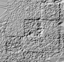
Box artifacts in a HiRISE DTM.
- CCD Seams: A HiRISE image is made up of 10 individual images, stitched together along their long edges. In a DTM, these seams can be visible as long lines. These seams are difficult to remove, and so are usually left unedited.
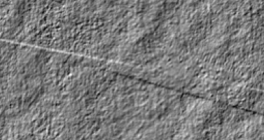
CCD seam artifacts in a HiRISE DTM.
- Faceted Areas: Areas that were very bland (low contrast) or deeply shadowed with low contrast and low signal may have a “faceted” look to them. Terrain in these areas may only generally approximate the shape of terrain.
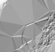
Facet artifacts in a HiRISE DTM.
- Manually Interpolated Areas: Some manual editing tools result in a geometric pattern due to interpolation from boundary posts. The user should be aware of these and compare the DTM to the images to understand the quality of the interpolation.
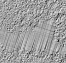
Manual interpolation artifacts in a HiRISE DTM.
What are the qualitative things to be aware of and watch for?
The general usability guidelines for HiRISE DTMs vary little from the guidelines presented for other Mars DTMs data sets (e.g., CTX DTMs). Therefore, we provide a single discussion on general usability that is replicated across these HiRISE data and the CTX DTMs. Issues such as jitter, long baseline undulations or tilts, and data gaps (albeit generally edited in HiRISE data) are present in both data sets.
There are a range of possible artifacts that may be encountered in DTMs. It is recommended to inspect the DTM and shaded-relief image to understand the quality. In some cases, it may be helpful to create your own shaded-relief images with a light source direction that exactly matches an orthoimage. Additionally, shaded relief with illumination from barely above the horizon can make subtle DTM features more obvious. Functions to create shaded relief images from DTMs are available in GIS software. We discuss the most common possible issues from the largest to the smallest scale.
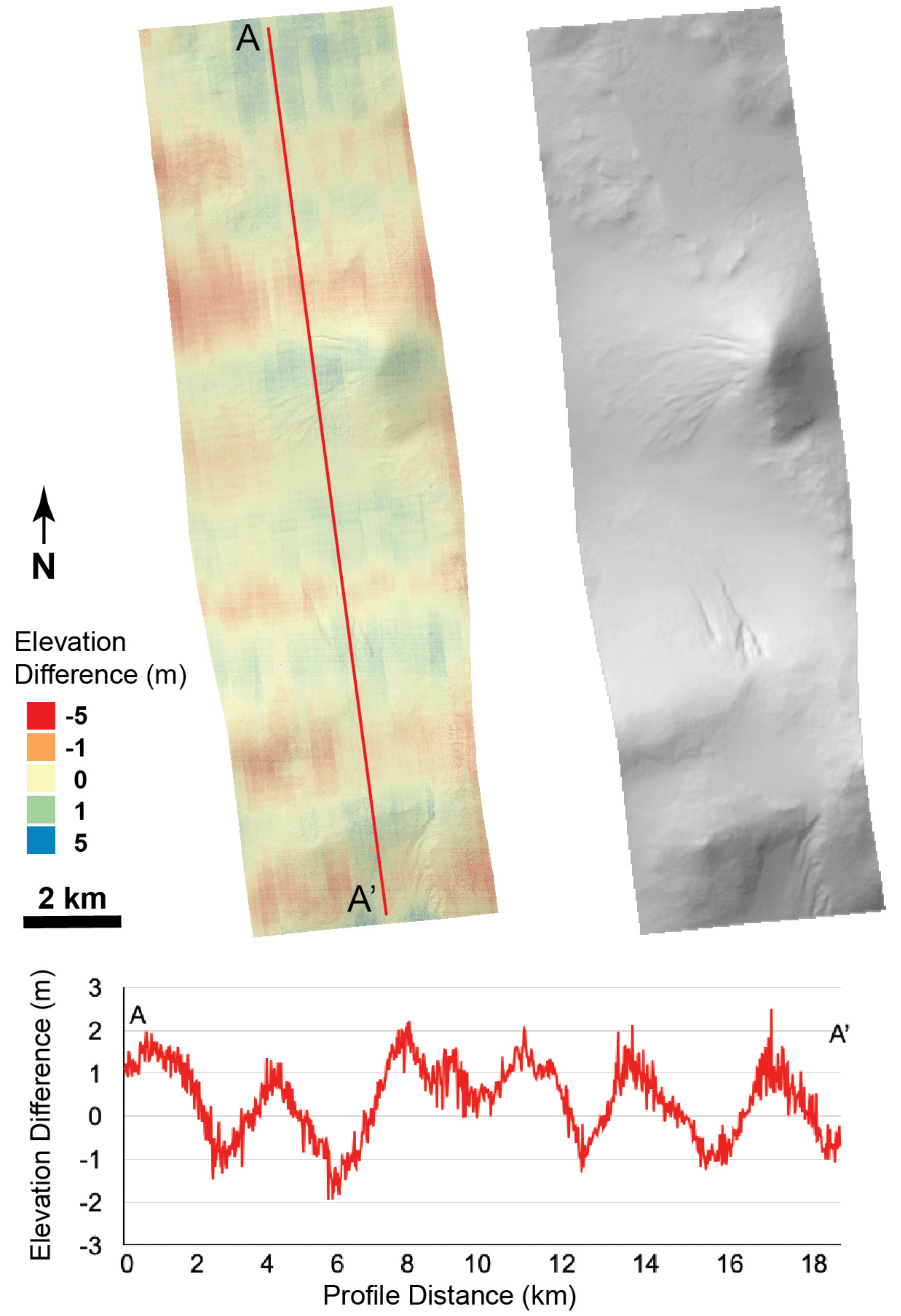
At large scales, the most likely source of error is incorrect long-baseline topography or tilt due to imperfect alignment with MOLA. This can be subtle and hard to discern, but even a small long-baseline slope offset can result in large topographic errors when propagated over tens of kilometers. These effects can best be detected by comparing absolute elevations with the MOLA DTM or individual tracks and looking for spatial patterns. For instance, a long-baseline slope may appear as a systematic variation in the MOLA-HiRISE offset across the DTM. Additionally, large-scale patterns in the topography such as multi-kilometer hills and valleys with no obvious correspondence to visible topographic features may relate to poor control to MOLA. Looking at a topographic profile that covers the DTM from end to end can show these sorts of features.
At medium scales, the most likely issue affecting a HiRISE DTM is jitter. Jitter effects appear as a “washboard” pattern in the DTM. They are usually easiest to see in shaded relief at medium resolution and over smooth terrain; it may be hard to notice if zoomed all the way in, especially if there is a slope. This pattern results from high-frequency vibrations on the MRO spacecraft while one or both of the images were being acquired, which means that the camera was not pointed quite where expected from the ancillary pointing information while solving for the topography. The amplitude and wavelength of jitter may vary along an image depending on what perturbations were happening on the spacecraft. Many HiRISE images are acquired in a high-stability mode that minimizes sources of vibration, but significant jitter can still occur.
Jitter figure from Sutton, et al. 2022 Revealing Active Mars with HiRISE Digital Terrain Models . Reproduced without alteration under the Creative Commons Attribution (CC BY) license .
At short wavelengths there are several issues to watch for. Comparing an orthoimage with shaded relief images is the best way to reveal small-scale artifacts, which appear as topographic features in the shaded-relief image with no corresponding feature in the corresponding orthoimage. Common small-scale artifacts include localized, discrete pits and bumps due to matching blunders, as well as a pebbled texture that is often pervasive with a low amplitude of a few meters, consistent with the expected vertical precision. The latter provides a background level of “noise” in the topography.
Animated GIF: Comparison of the shaded-relief image and orthoimage for part of D21_035270_1829_XI_02N199W__D20_035204_1829_XI_02N199W_DEM. Note both local artifacts (bumps and pits) and the ubiquitous pebbled texture. The latter is usually low-relief and has little effect unless you are interested in slopes at short baselines, as it can be a significant source of error for those slopes.
If you are interested in small features, it is also a good idea to check whether they were effectively resolved in the DTM. Sometimes small-scale features may be smoothed out during the image matching process or be missed entirely. Small features may also be distorted even if they are visible, due to errors: a three-meter vertical error (typical expected precision for these DTMs) can seriously distort a ten-meter-high hummock but is a minor effect in a 100-m-deep crater. Additionally, since the point cloud that initiates the DTM is created by matching patches of images, small features may be slightly widened while having the extremes of the topography reduced.
Animated GIF: Comparison of the shaded-relief image and orthoimage for another part of D21_035270_1829_XI_02N199W__D20_035204_1829_XI_02N199W_DEM. The first part of the comparison shows examples of some small impact craters that were effectively resolved by the DTM. The second part shows craters that were partially resolved or not resolved at all. For partially resolved features, there does appear to be a feature in the DTM but it may not have the right depth or diameter, while the unresolved crater simply does not appear in the shaded relief. The final part of the comparison shows artifacts: features that are present in the DTM but not in the image.
DTMs may have gaps in areas where the stereo matching algorithm was unable to derive a good solution. These appear as “nodata” points and can range from small pinhole gaps to large swaths (often in rectangular tile shapes). Outlier points along the edge of the DTM or detached from the main DTM surface can also occur, with elevation values that are very discordant with the rest of the surface. These outlier points should not be used for measurements.
What should you do if you encounter one of these artifacts? It depends on the artifact and the topic that you are interested in, and should be considered on a case-by-case basis. For instance, even substantial long-baseline tilts usually do not have much effect on local topography, so you may be able to measure the height of a hill or depth of a crater, especially if you can correct for the tilt. Slope measurements will be off by up to the amount of the long-baseline tilt (depending on the direction), so a one-degree long-baseline slope will not have much effect on a steep crater wall. On the other hand, if you are interested in how a lava flow moved across the entire DTM, even subtle long-baseline slopes could cause important errors. Since the true long-baseline slope over the area covered by a typical HiRISE DTM is usually low, a subtle tilt may change its magnitude and direction meaningfully. In contrast, widespread noise like the pebbled textures shown above can cause inaccurate slope measurements at short baselines but usually averages out over longer scales. For example, a 3-meter topographic error could turn flat terrain into a 9º slope over a 20-m baseline but would only result in a <1º error over 200 m. It is always advisable to inspect the data and assess what kinds of errors may exist and whether the DTM is usable for your needs.
Though the user can operate around large-scale and systematic small-scale issues, no such option is available for small-scale discrepancies. Features that were not resolved in the DTM cannot be measured at all and artifacts that may locally create false features that should not be measured.
Since DTMs are controlled individually and the control process makes a best estimate of the alignment with MOLA in each case, adjacent (overlapping) DTMs are unlikely to line up perfectly. They are aligned independently with different parts of the MOLA data and the MOLA resolution is much lower. This can result in horizontal and vertical offsets and would appear as cliffs if the two or more DTMs were combined.
Finally, the HiRISE DTMs include a Figure of Merit (FOM) image that should be consulted before and during DTM use. The FOM identified areas with good matcher correlation, low correlations, manual edits, interpolation and extrapolation, saturated data pixels, shadowed data pixels, no data pixels, and suspicious terrains. The FOM is the definitive source of pixel level provenance for the DTM.
Orthorectified images associated with each DTM are available.
The HiRISE images that served as input stereo pairs for these data were most often collected concurrently with CTX data. Such coordinated observations can be particularly useful because the viewing geometry, surface illumination, and atmospheric conditions are the same. HiRISE and CRISM data are available from the PDS but the standard products have not been orthorectified at the scale of the CTX DTMs and orthoimages; therefore, they will not align precisely if they are imported into GIS software and there will be some geometric distortion of non-orthorectified data. Orthorectified HiRISE images may not align perfectly either as they are aligned to a different DTM.
These data are released under the CC0-1.0 license , meaning you can copy, modify, and distribution these data without permissions. We ask that you cite these data if you make use of them. The citation to be used is:
- Kirk, R., Howington-Kraus, E., Rosiek, M., Anderson, J., Archinal, B., Becker, K., Cook, D., Galuszka, D., Geissler, P., Hare, T., Holmberg, I., Keszthelyi, L., Redding, B., Delamere, W., Gallagher, D., Chapel, J., Eliason, E., King, R. & McEwen, A. (2008). Ultrahigh resolution topographic mapping of Mars with MRO HiRISE stereo images: Meter-scale slopes of candidate Phoenix landing sites. Journal of Geophysical Research: Planets, 113(E3). https://doi.org/https://doi.org/10.1029/2007JE003000
- Kirk, R., Fergason, R., Redding, B., Galuszka, D., Smith, E., Mayer, D., Hare, T. & Gwinner, K. (2020). Evaluating Stereo DTM Quality at Jezero Crater, Mars With HRSC, CTX, and HiRISE Images. The International Archives of the Photogrammetry, Remote Sensing and Spatial Information Sciences, XLIII-B3-2020. 1129–1136. https://doi.org/10.5194/isprs-archives-XLIII-B3-2020-1129-2020
- Mattson, S., Heyd, R., Fennema, A., Kirk, R., Cook, D., Becker, K., McEwen, A. & Boyd, A. (2012). High-Precision Geometrically Corrected HiRISE Images.
- McEwen, A., Eliason, E., Bergstrom, J., Bridges, N., Hansen, C., Delamere, W., Grant, J., Gulick, V., Herkenhoff, K., Keszthelyi, L., Kirk, R., Mellon, M., Squyres, S., Thomas, N. & Weitz, C. (2007). Mars Reconnaissance Orbiter’s High Resolution Imaging Science Experiment (HiRISE). Journal of Geophysical Research: Planets, 112(E5). https://doi.org/https://doi.org/10.1029/2005JE002605
- Smith, D., Zuber, M., Frey, H., Garvin, J., Head, J., Muhleman, D., Pettengill, G., Phillips, R., Solomon, S., Zwally, H., Banerdt, W., Duxbury, T., Golombek, M., Lemoine, F., Neumann, G., Rowlands, D., Aharonson, O., Ford, P., Ivanov, A., Johnson, C., McGovern, P., Abshire, J., Afzal, R. & Sun, X. (2001). Mars Orbiter Laser Altimeter: Experiment summary after the first year of global mapping of Mars. Journal of Geophysical Research: Planets, 106(E10). 23689–23722. https://doi.org/https://doi.org/10.1029/2000JE001364
- Sutton, S., Heyd, R., Fennema, A., McEwen, A., Kirk, R., Howington-Kraus, E. & Espinoza, A. (2015). HiRISE Digital Terrain Models: Updates and Advances.
- Sutton, S., Chojnacki, M., McEwen, A., Kirk, R., Dundas, C., Schaefer, E., Conway, S., Diniega, S., Portyankina, G., Landis, M., Baugh, N., Heyd, R., Byrne, S., Tornabene, L., Ojha, L. & Hamilton, C. (2022). Revealing Active Mars with HiRISE Digital Terrain Models. Remote Sensing, 14(10). 2403.