

Voyager Individual Photogrammetrically Controlled Images
These data can be accessed in three ways:The twin Voyager 1 and Voyager 2 spacecraft launched in August (Voyager 2) and September (Voyager 1) of 1977 and reached the Jupiter system in March (Voyager 1) and July (Voyager 2) of 1979, where they acquired images of the Galilean satellites before continuing on to Saturn. Each spacecraft was identically equipped with both wide-angle and narrow-angle slow-scan vidicon cameras that comprised the Imaging Science Subsystem (ISS). Each camera used 800 scan lines per frame, and 800 picture elements per line. The wide-angle cameras nominally had a 200-mm focal length, 55.6 55.6-mrad field of view, and a 69.4 rad angle subtended by each scan line. The narrow-angle cameras nominally had a 1500-mm focal length, a 7.5 7.5-mrad field of view, and 9.25-rad angle subtended by each scan line. The images include fiducial markers (reseaux) and corner markers used for calibration measurements (e.g., geometric camera distortion), which must be removed before scientific use. Each camera also included an eight-position filter wheel, which enabled color images to be generated when images taken through different filters are combined. See ( Citation: Smith, Briggs & al., 1977 Smith, B., Briggs, G., Danielson, G., Cook, A., Davies, M., Hunt, G., Masursky, H., Soderblom, L., Owen, T., Sagan, C. & Suomi, V. (1977). Voyager imaging experiment. Space Science Reviews, 21(2). 103–127. https://doi.org/10.1007/BF00200847 ) for additional details on the Voyager cameras.
Although the Voyager spacecraft returned images of nearly all of Europa’s surface (to ± 80° latitude), “high resolution” images (pixel scales < 2 km/pixel) are limited to the anti-Jovian and southern hemispheres, where both Voyagers made their closest approach (Fig. 1). Europa was subsequently visited by the Galileo spacecraft ( Citation: Belton, Head & al., 1996 Belton, M., Head, J., Ingersoll, A., Greeley, R., McEwen, A., Klaasen, K., Senske, D., Pappalardo, R., Collins, G., Vasavada, A., Sullivan, R., Simonelli, D., Geissler, P., Carr, M., Davies, M., Veverka, J., Gierasch, P., Banfield, D., Bell, M., Chapman, C., Anger, C., Greenberg, R., Neukum, G., Pilcher, C., Beebe, R., Burns, J., Fanale, F., Ip, W., Johnson, T., Morrison, D., Moore, J., Orton, G., Thomas, P. & , R. (1996). Galileo’s First Images of Jupiter and the Galilean Satellites. Science, 274(5286). 377–385. https://doi.org/10.1126/science.274.5286.377 ) , which returned higher resolution (smaller pixel scale) images of much of the satellite. However, because of the failure of Galileo’s high-gain antennae, the total data volume returned by that mission was limited. In some regions of Europa, Voyager images provide higher-resolution observations of the surface than Galileo. This dataset therefore remains a critical resource to understand Europa’s surface geology. To create these data, we used the USGS’ photogrammetric software, ISIS, to improve the geographic locations of 221 Voyager images and the entire Galileo image dataset. The geometric correction enables researchers to utilize most of the Voyager ISS images at their original pixel scale (see https://stac.astrogeology.usgs.gov/docs/data/jupiter/europa/galileo_individual_images/ for the Galileo images), enabling robust scientific investigations and mission planning.
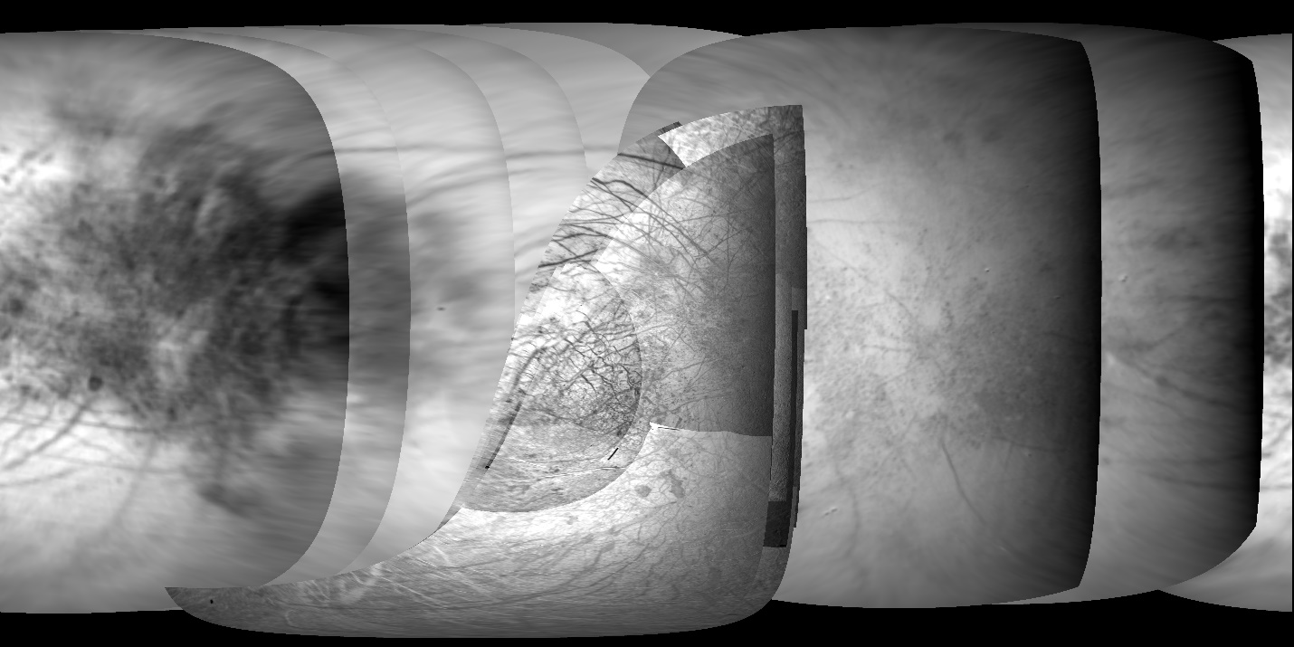
Figure 1: Voyager image mosaic of Europa illustrating the spatial variability in image quality. The mosaic used an equirectangular projection, covering 0–360° E and ± 90° north and south. Images are ordered by pixel scale and no blending was used, so that image seams are clear. The highest resolution (smallest pixel scale) images are of the anti-Jovian hemisphere (near longitude 180° at the map center).
The Voyager images range in scale from 1.63 km/pixel to 32 km/pixel, with the highest resolution images concentrated at 180 E. Raw Voyager images were downloaded from the Planetary Data System (PDS, https://pds-imaging.jpl.nasa.gov/portal/voyager_mission.html ) in compressed format (*.imq) and ingested into ISIS with the voy2isis command to create ISIS cubes (i.e., images in .cub format). Reconstructed SPICE kernels (i.e., the default kernels) were then applied (we used the pck00010_msgr_v23.tpc planetary constants kernel, or PCK). In most cases, the reconstructed Voyager SPICE is so inaccurate that it does not coincide with the location of the body in the image. The SPICE therefore had to be manually adjusted using the ISIS deltack application before the images could be used (see ( Citation: Bland, Weller & al., 2021 Bland, M., Weller, L., Archinal, B., Smith, E. & Wheeler, B. (2021). Improving the Usability of Galileo and Voyager Images of Jupiter’s Moon Europa. Earth and Space Science, 8(12). e2021EA001935. https://doi.org/https://doi.org/10.1029/2021EA001935 ) for details). Once the SPICE was corrected, we applied a geometric correction (the ISIS application findrx) and the standard Voyager radiometric calibration (the ISIS application voycal). Image reseaux were then removed (the ISIS application remrx).
The Voyager images were photogrammetrically controlled together with Europa images from the Galileo mission. Raw Galileo images and labels were downloaded from the PDS ( https://pds-imaging.jpl.nasa.gov/volumes/galileo.html ) and ingested into ISIS using the application gllssi2isis. Reconstructed SPICE kernels were applied using the ISIS spiceinit application. A standard radiometric calibration (the ISIS application gllssical) and noise filter (the ISIS application noisefilter) was applied, and the edge of each image was then trimmed by 2 pixels (the ISIS application trim). In some cases, image downlink was interrupted mid-transmission and had to be completed later, with the result that lines from a single frame are split into multiple image files. These images were reconstructed using the ISIS application handmos, which combines two ISIS cubes by line/sample.
A global network of image tie points (a control network) was developed for the Voyager and Galileo images using ISIS. The control network is the input to the photogrammetric control process, in which a least-square bundle adjustment is performed to triangulate the ground coordinates (latitude, longitude, and radius) of each tie point and minimize location residuals globally. The ISIS application jigsaw was used to perform all the bundle adjustments. To create a global control network for Europa images, three independent networks were first generated: a Voyager-only network, a Galileo-only network, and a bridge network that included key Voyager and Galileo images. Each of these networks was bundle adjusted separately to ensure a clean network (i.e., free from image mis-registrations). The three clean networks were then merged into a single network and bundled together to update image locations. The final bundle adjustment solved for camera angles (including twist) using a priori constraints of 1 degree on camera angles and 500 m in radius. The orientation of Europa was then adjusted (parametrized as the prime meridian offset Wo) to ensure the data are aligned with the IAU-defined coordinate system for Europa (i.e., the longitude of the center of the crater Cilix must be at 182o W / 178o E).
The final bundle solution included 694 Galileo and Voyager images, of which 221 were from Voyager. We then replaced the null pixels resulting from reseaux removal with data interpolated from surrounding pixels using a sequence of lowpass filters. The ISIS application cam2map was used to project each image to an equirectangular projection with Europa’s mean radius of 1,560.8 km ( Citation: Archinal, Acton & al., 2018223 Archinal, B., Acton, C., A'Hearn, M., Conrad, A., Consolmagno, G., Duxbury, T., Hestroffer, D., Hilton, J., Kirk, R., Klioner, S., McCarthy, D., Meech, K., Oberst, J., Ping, J., Seidelmann, P., Tholen, D., Thomas, P. & Williams, I. (2018, 2, 23). Report of the IAU Working Group on Cartographic Coordinates and Rotational Elements: 2015. Celestial Mechanics and Dynamical Astronomy, 130(3). 22. https://doi.org/10.1007/s10569-017-9805-5 ) and the original pixel scale of the image. Images are in an east-positive, planetocentric, 0–360o longitude coordinate system, which was adopted for consistency with the upcoming Europa Clipper and JUICE missions. Additional details can be found in ( Citation: Bland, Weller & al., 2021 Bland, M., Weller, L., Archinal, B., Smith, E. & Wheeler, B. (2021). Improving the Usability of Galileo and Voyager Images of Jupiter’s Moon Europa. Earth and Space Science, 8(12). e2021EA001935. https://doi.org/https://doi.org/10.1029/2021EA001935 ) . The projected images were trimmed by photometric angle to remove regions beyond the limb (emission angle > 90°) and terminator (incidence angle > 90°).
- Voyager 1 and Voyager 2 individual projected images (equirectangular projection)
- ISIS label files
- Original PDS label files
- ISIS history files tracking the data provenance
Final bundle adjustment yielded root mean square (RMS) uncertainty (over all points) of 0.32 pixels. This value should be thought of as the global uncertainty in the location of images relative to one another, and uncertainty can be higher in many locations. Given the pixel scale of the Voyager images, the uncertain is no better than 2 km in ground coordinates. The data are also tied to Europa’s geodetic reference system. The center of the crater Cilix, which defines the reference system at 182o W (178o E), is located at 181.9991414oW (178.0008586oE) in the combined Voyager and Galileo mosaic. The difference is approximately equivalent to 23 m. The highest resolution Galileo images of Cilix have a pixel scale of 63 m/pixel, so the location is “known” to a fraction of a pixel. The precision therefore exceeds that with which the center of Cilix (a 19-km-diameter crater) is known, especially given the natural irregularity of the crater rim. However, given that the data set is tied to the reference frame only at a single point, the certainty with which absolute coordinates are known degrades with distance from Cilix (generally as the where N is the number of images away from Cilix).
The individual images provide the user with a simple means to use single images with updated image locations in, for example, a GIS environment or machine learning software. This includes analyses that combine multiple images from different datasets (e.g., Voyager and Galileo) in a spatially consistent way. The individual images have been calibrated to I/F and can be combined to create multi-band color image products. However, no photometric correction has been applied. These mosaics should therefore not be used, under any circumstances, for quantitative or qualitative analysis of albedo variations, except under the limited circumstances of relative albedo differences over small spatial scales within a single image.
Voyager images include fiducial marks used to geometrically calibrate the camera. These marks have been removed and replaced by data interpolated from surrounding pixels. The user should be aware that apparent features near the pixel scale of the image may be the result of this interpolation. The user should also be aware that no attempt was made to make the mosaics spatially consistent with existing data products, such as the 500 m/pixel, USGS Galileo-Voyager mosaic ( https://astrogeology.usgs.gov/search/map/Europa/Voyager-Galileo/Europa_Voyager_GalileoSSI_global_mosaic_500m) , or Dr. Paul Schenk’s mosaics ( https://repository.hou.usra.edu/handle/20.500.11753/1412) .
Traditional, global mosaics of Europa are available from the USGS ( https://astrogeology.usgs.gov/search/map/Europa/Voyager-Galileo/Europa_Voyager_GalileoSSI_global_mosaic_500m ) and Paul Schenk ( https://repository.hou.usra.edu/handle/20.500.11753/1412) .
These data are released under the CC0-1.0 license , meaning you can copy, modify, and distribution these data without permissions. We ask that you cite these data if you make use of them. The citation to be used is:
Bland, M. T., Weller, L. A., Archinal, B. A., Smith, E., Wheeler, B, H., 2021. Improving the usability of Galileo and Voyager images of Jupiter’s moon Europa. Earth and Space Sci. 8, e2021EA001935. http://doi.org/10.1029/2021EA001935
- Archinal, B., Acton, C., A'Hearn, M., Conrad, A., Consolmagno, G., Duxbury, T., Hestroffer, D., Hilton, J., Kirk, R., Klioner, S., McCarthy, D., Meech, K., Oberst, J., Ping, J., Seidelmann, P., Tholen, D., Thomas, P. & Williams, I. (2018, 2, 23). Report of the IAU Working Group on Cartographic Coordinates and Rotational Elements: 2015. Celestial Mechanics and Dynamical Astronomy, 130(3). 22. https://doi.org/10.1007/s10569-017-9805-5
- Belton, M., Head, J., Ingersoll, A., Greeley, R., McEwen, A., Klaasen, K., Senske, D., Pappalardo, R., Collins, G., Vasavada, A., Sullivan, R., Simonelli, D., Geissler, P., Carr, M., Davies, M., Veverka, J., Gierasch, P., Banfield, D., Bell, M., Chapman, C., Anger, C., Greenberg, R., Neukum, G., Pilcher, C., Beebe, R., Burns, J., Fanale, F., Ip, W., Johnson, T., Morrison, D., Moore, J., Orton, G., Thomas, P. & , R. (1996). Galileo’s First Images of Jupiter and the Galilean Satellites. Science, 274(5286). 377–385. https://doi.org/10.1126/science.274.5286.377
- Bland, M., Weller, L., Archinal, B., Smith, E. & Wheeler, B. (2021). Improving the Usability of Galileo and Voyager Images of Jupiter’s Moon Europa. Earth and Space Science, 8(12). e2021EA001935. https://doi.org/https://doi.org/10.1029/2021EA001935
- Smith, B., Briggs, G., Danielson, G., Cook, A., Davies, M., Hunt, G., Masursky, H., Soderblom, L., Owen, T., Sagan, C. & Suomi, V. (1977). Voyager imaging experiment. Space Science Reviews, 21(2). 103–127. https://doi.org/10.1007/BF00200847